
Fault Current Estimation and Calculation: A Practical Guide for Power Engineers
- Brandon Lackey, PE

- Apr 19, 2025
- 3 min read
Updated: Apr 26, 2025
Estimating and Calculating Fault Current: A Practical Guide for Engineers
Fault current estimation and calculation are foundational to designing safe, reliable, and efficient power systems. Whether planning protection schemes, sizing equipment, or ensuring compliance with industry standards, understanding fault current behavior is critical.
At GreenPowr, we approach fault current analysis with precision because it directly impacts system resilience, arc flash safety, and equipment longevity.
Let's dive into how engineers estimate and calculate fault current, and why it matters.
Why Fault Current Matters
Fault current is the sudden surge of electrical current that flows through a system when an abnormal condition, such as a short circuit or ground fault, occurs. Proper fault current calculations are essential for:
Sizing circuit breakers, fuses, and protective relays
Determining busbar, conductor, and transformer ratings
Setting protection coordination and arc flash boundaries
Preventing catastrophic equipment failures
Without accurate fault current analysis, power systems are exposed to dangerous conditions and costly downtime.
Types of Faults
Before calculating, it's important to recognize the common fault types:
Three-phase fault (symmetrical fault): All three phases short together — highest magnitude fault.
Single line-to-ground fault (SLG): One phase shorts to ground.
Line-to-line fault (LL): Two phases short together.
Double line-to-ground fault (LLG): Two phases short to ground.
Each fault type has a different current magnitude and impact on the system, so calculations must be fault-specific.
Estimating Fault Current: Quick Methods
For rough sizing early in design, engineers often use simple estimation formulas:
Three-Phase Fault Current Estimate:
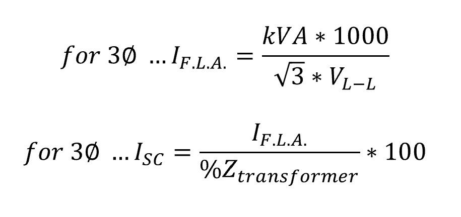
Example: If the utility 3-phase short-circuit at the service point is 6 MVA and the system voltage is 13.8 kV and the transformer impedance is 5%:

Quick estimates are useful but must be refined during detailed engineering.
Detailed Fault Current Calculation
Accurate fault current calculation requires accounting for all system impedances, including:
Source (utility or generator)
Transformers (positive, negative, and zero sequence impedances)
Cables and bus duct impedance
Motor contribution (if applicable)
Grounding system impedance (especially critical for LRG, HRG, or solidly grounded systems)
Per Unit System Approach:
Normalize all impedances to a common base (MVA, kV)
Add impedances in series for the fault path
Use sequence networks for asymmetrical faults (SLG, LLG, LL)
Software Tools: Engineers typically use programs like ETAP, SKM PowerTools, or EasyPower for system-wide fault studies, incorporating ANSI/IEEE standards (e.g., IEEE C37 series).
Motor Contribution to Fault Current
Motors, especially large induction motors, contribute additional current during the initial fault period. Typical characteristics:
Motor fault contribution = 4–6 times motor full-load current.
Contribution decays rapidly within a few cycles.
Motor fault current must be included to ensure protective devices interrupt faults before damage occurs.
Fault Current and Arc Flash Considerations
High fault currents increase the severity of arc flash hazards. Fault current data is essential for:
Arc flash incident energy analysis (IEEE 1584 method)
Defining Personal Protective Equipment (PPE) categories
Determining safe working distances
Accurate fault current calculation directly improves worker safety and regulatory compliance.
Key Standards for Fault Current Calculation
When performing studies, engineers reference:
IEEE Std 141 (Red Book): Electric Power Distribution for Industrial Plants
IEEE Std 399 (Brown Book): Industrial and Commercial Power Systems Analysis
IEEE Std 551 (Gold Book): Reliability of Industrial and Commercial Power Systems
IEEE Std 242 (Buff Book): Protection and Coordination
ANSI/IEEE C37 Series: Application guide for switchgear, relays, and protection devices

Comments